Posted on
While thin film deposition is often used to create a continuous coating on a substrate, there are many applications where a patterned coating is required. These patterns create bumps, trenches or ridges across the surface of the substrate. This coating type is used for 3D applications, such as electrical interconnects. Focal plane arrays with high-density pixels for LiDAR, video imaging and spectrometry are just a few application examples.
The Lift-Off Process
With a lift-off process, the coating is applied through a masking agent, so that only the desired areas are coated through the open areas to fill out the desired pattern. However, the mask then needs to be lifted off. A clean fill is required to ensure a high yield lift-off, so that the entire desired patterned coating remains and only the excess coating is removed with the mask. Depending on the application, factors such as pixel size, pixel density, feature size and sidewall morphology all needed to be accounted for, and may affect performance for the end-user application.
Considerations for High Yield Lift-Off
There are a number of thin film deposition process considerations that may affect lift-off, and the yield for the entire process:
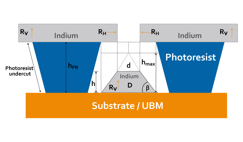
- Pattern specification: If the dimensions for the pattern are large, it may be relatively easy to achieve good lift-off with just a thin sheet of metal as a masking agent. However, a pattern with smaller dimensions or sharper line resolution will require photoresist. The photoresist process is usually designed to leave an overhanging edge so that there’s a small gap between the edge of the coated line and the photoresist coverage. The undercut angle here, which creates a negative slope, is the most important aspect for good lift-off.
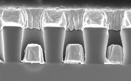
- Geometry: Proper system geometry helps control the throw distance and deviation so that the substrate is hit at a direct angle. A longer throw distance from the source ensures that the masked substrate is hit at a perpendicular angle. At a maximum, there should be a 7° deviation from the direct line of sight, so that the substrate is hit perpendicularly. This leads to a clean fill with no contact between the coating and the bottom of the photoresist (as shown in the photo below), and in turn boosts the yield for lift-off.
- Uniformity: Uniform openings are an important factor for good lift-off. Closure uniformity, which leads to consistency in the size and height of the bumps being created, can have a major effect on yield. Any variance in bump height size can affect performance for end-user applications.
- Substrate material: A metallic layer may sometimes cause optical interference, which can result in pattern distortion and affect yield.
There are also two other process factors that can affect your lift-off:
- Pressure: You need a low pressure inside the chamber to achieve a long mean free path, which refers to the average distance an atom or molecule will travel in a straight line before colliding with another molecule. A shorter mean free path could affect the deviation and diminish the fill.
- Temperature: Deviations from the optimum process temperature for the substrate can decrease lift-off yield, so you need to ensure good thermal control to prevent this.
Improving Lift-Off with Collimation Control
Using an indium bump deposition technique that is highly collimated will give you the control you need over many of these factors to improve your lift-off yield. Collimation control eliminates edge effect and enables a clean deposit of indium. It also improves closure uniformity and offers full control of the deposition angle of incidence.
For more details on how collimation control improves lift-off, download our infographic, 3 Considerations for Indium Bump Deposition.